Introduction
Amplifiers play a crucial role in today’s audio systems, delivering clear and powerful sound. Among the different types of amplifiers available, MOSFET amplifiers are widely appreciated for their high efficiency and superior audio quality. In this article, we will discuss a powerful 500W MOSFET amplifier circuit diagram that utilizes four pairs of IRFP448 MOSFETs in the output section, along with 2SD401, 2SB546, and BF258 transistors in the driver and preamplifier sections. This circuit is designed to provide an immersive audio experience, making it perfect for home theaters or large event setups.
Specifications of IRFP448 MOSFET:
The IRFP448 MOSFET is a high-power N-Channel transistor specifically designed for audio amplification applications. Here are its key specifications:
- Maximum Drain-Source Voltage: 500V
- Continuous Drain Current: 14A
- Power Dissipation: 195W
- Drain-Source Voltage (ON): 0.77V
- Gate Threshold Voltage: 2V to 4V
- Input Capacitance: 1800pF
- Output Capacitance: 280pF
- Total Gate Charge: 120nC
500W MOSFET Amplifier Circuit Diagram
This project can be built using a few basic components. The circuit diagram of this project is shown below.


Caution: Website contains information on high voltage circuits. Proceed at your own risk, ensuring proper knowledge and precautionary measures to prevent electric shock or injury.
More Circuit Layouts


Components List of 500W MOSFET Amplifier Circuit Diagram
Following is the list of all components used in this project:
- IRFP448 MOSFET x 8
- 2SD401 Transistor x 4
- 2SB546 Transistor x 3
- 2SC1061 Trnsistor x 1
- BF258 Transistor x 3
- 1N4148 Diode x 4
- 1jN4005 Diode x 2
- 1Ω/10W Resister x 4
- 0.2Ω/5W Resister x 4
- 1k Resister x 9
- 330Ω Resister x 2
- 10Ω Resister x 1
- 220Ω Resister x 5
- 33k/1W Resister x 2
- 18k Resister x 1
- 680Ω Resister x 2
- 390Ω Resister x 1
- 47Ω Resister x 1
- 240Ω Resister x 1
- 22Ω Resister x 1
- 22k Resister x 1
- 10uF Capacitor x 1
- 220pF Capacitor x 1
- 0.047uF Capacitor x 2
- 100uF Capacitor x 1
- 100pF Capacitor x 1
- 0.01uF Capacitor x 1
- 560pF Capacitor x 1
Explanation of 500W MOSFET Amplifier Circuit Diagram
The 500W MOSFET amplifier circuit consists of several key sections that work together to amplify the incoming audio signal and deliver the desired power output. Here is a brief overview of each section:
- Preamplifier Section: The preamplifier section consists of transistors BF258 transistors. These transistors function as a differential amplifier, amplifying the weak audio signals from the source and providing a higher voltage and current gain.
- Driver Section: The driver section amplifies the preamplified signals further and provides the necessary drive to the power MOSFETs in the output stage. The 2SD401 & 2SB546 transistors are used in this section to ensure a high-quality audio signal transfer.
- Output Section: The heart of this amplifier circuit is the output section, which utilizes four pairs of IRFP448 MOSFETs. The IRFP448 MOSFETs are renowned for their high power handling capabilities and low ON-resistance. These characteristics allow for efficient power transfer and minimal distortion, ensuring excellent audio performance even at high power levels.
Conclusion
The 500W MOSFET amplifier circuit diagram utilizing four pairs of IRFP448 MOSFETs, along with 2SD401, 2SB546, and BF258 transistors, offers a powerful and efficient solution for audio amplification. By incorporating high-quality components and a well-designed circuit, this amplifier ensures minimal distortion and superior audio quality. Whether you are looking to enjoy immersive sound in your home theater or require a high-power audio setup for events, this amplifier circuit is a perfect choice. Its robust design and reliable performance make it suitable for a wide range of audio applications.
More projects, You may like:
- Video Transmitter DIY Homemade FM Radio Transmitter
- Adjustable Power Supply DIY Battery Charger
- 12V-220V 500 Watt inverter DIY Homemade
- MPPT Solar Charge Controller DIY Homemade
- DIY LA4440 bass amplifier homemade
For more project and circuit diagrams, you can go through the Schematics in the main menu where you can find many interesting projects and circuit diagrams like audio amplifier circuits, voltage booster circuit, battery charger circuit and timer circuits etc. Feel free to check them out!

Thank you for visiting the article.
You may also like:
![TDA7294 High-Efficiency Power Amplifier Circuit]()
TDA7294 High-Efficiency Power Amplifier Circuit
![2N3055 Power Amplifier Circuit Diagram]()
2N3055 Power Amplifier Circuit Diagram
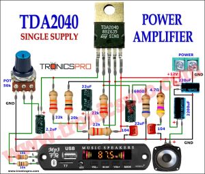
![30W TDA2040 Power Amplifier Circuit Diagram]()
30W TDA2040 Power Amplifier Circuit Diagram
![600W Audio Power Amplifier Circuit using 2SC5200 & 2SA1943]()
600W Audio Power Amplifier Circuit Diagram using 2SC5200 & 2SA1943 - APEX BX22
![68W Audio Amplifier LM3886 Circuit Diagram]()
68W Audio Amplifier using LM3886 Circuit Diagram
![Super Bass Tone Control Circuit Diagram]()
Bass Tone Control Circuit Diagram using LM324 Opamp
![One Transistor Audio Mixer Circuit Diagram]()
One-Transistor Audio Mixer Circuit Diagram
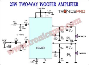
![20W Two-Way Woofer Amplifier TDA2005 Circuit Diagram]()
20W Two-Way Woofer Amplifier TDA2005 Circuit